DAM & CANAL GATE
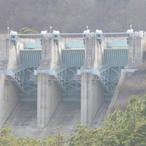
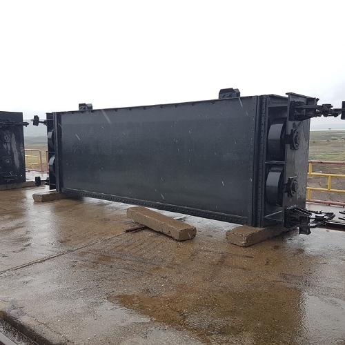
Radial Gate
A side view of a Radial gate resembles a slice of pie with the curved part of the piece facing the source or upper pool of water and the tip pointing toward the destination or lower pool. The curved face or skin plate of the gate takes the form of a wedge section of cylinder. The straight sides of the pie shape, the trunnion arms, extend back from each end of the cylinder section and meet at a trunnion which serves as a pivot point when the gate rotates. Pressure forces acting on a submerged body act perpendicular to the body’s surface. The design of the Radial gate results in every pressure force acting through the centre of the imaginary circle of which the gate is a section, so that all resulting pressure force acts through the pivot point of the gate, making construction and design easier. When a Radial gate is closed, water bears on the convex (upstream) side. When the gate is rotated, the rush of water passing under the gate helps to open and close the gate. The rounded face, long radial arms and trunnion bearings allow it to close with less effort than a flat gate. Radial gates are usually controlled from above with a chain/gearbox/electric motor assembly.
Radial gates are rotary gates consisting of cylindrical sections. They may rotate vertically or horizontally. Radial gates are a vertical design that rotates up to allow water to pass underneath. Low friction trunnion bearings, along with a face shape that balances hydrostatic forces, allow this design to close under its own weight as a safety feature.
Vertical Lift Gate


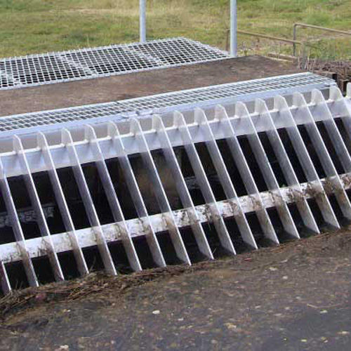
Sluice Gate
Stop Log Gate